Open topic with navigation
InterpaLog 
InterpaLog is a multi-well, two-dimensional log modeling tool used to
create accurate seismic section models. Create
a model from your WinPICS synthetic seismograms using the cross-sectioning
capability of InterpaLog. Define or select a seismic filter that will
create a seismic section based on the correlated logs. These seismic sections
can then be sent back to WinPICS and displayed as a selectable 2D line
on the map window.
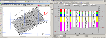
The InterpaLog bridge is launched from the WinPICS basemap. Select
a series of wells; send them to InterpaLog as a geological cross section.
Modify
the cross section and the geophysical parameters to accurately reflect
your geological concept, and create the interpolated log model. The
model seismic traces are then returned to the WinPICS basemap as pseudo
2D seismic line with the model correlations saved as seismic horizons.
The horizons on the model accurately track your geological boundaries
and are not forced to be simply peaks or troughs or zero crossings. Use
the WinPICS correlation polygon to make comparisons between your model
and seismic data. Enhanced
model analysis is available using amplitude maps for comparison and the
full suite of WinPICS seismic attributes. The
2D model may even be used with the WinPICS similarity mapping pattern
recognition algorithms.
For more detailed information, refer to the InterpaLog
Users Guide, which can be found in WinPICS on the Application toolbar under .  View image

Sending your WinPICS Synthetics to InterpaLog (Overview)
- Select
the InterpaLog
 icon on the Earth Tools toolbar.
- Click on the first synthetic seismogram on your WinPICS basemap. Move
your cursor over the next synthetic and continue clicking on each
synthetic in the order that you want them to appear in InterpaLog.
- Once
you have completed selecting the synthetics, right-click the WinPICS Map
window and select
(D)
from the shortcut menu to launch InterpaLog. The
Model Setup dialog box opens.
- Click <OK> to continue. The
Log Order dialog box opens.
- Click
<OK> to continue. The
Model Clipping window will opens.
- Click <OK> to continue.
- If
needed, rearrange the order of the wells in the selection by using the
Select Wells
 tool.
Click on a log to select it, then drag it to a new location.
- Click
the Correlation Editor
 button to display a list of tops for each well, and the elevation
for each top. From this window you can turn tops on/off, edit tops elevations,
create new correlations and interpolate tops between wells.
- Click <OK> to continue.
- To
create a new surface, click the New Event
 button. Choose the type of event you wish to create on the
General tab, and any comments
on the Notes tab. Click <OK> to close the New Event window. The
cursor will then change to a drawing tool. The drawing tool will then
behave like a top picker while hovering over the well track, and a freehand
drawing tool when hovered between the well tracks. Select <Esc>
key when you have completed drawing the correlation.
- To
extend a correlation, select the surface you want to extend by clicking
the Select Surfaces
 button, and then clicking on the surface to extend. Select
the Mouse Input
  button and draw the correlation, then click the Extend
Edges
  button to build the model.
- Editing
existing surfaces between wells can be performed by selecting the active
event, and choosing the Edit Surface
 tool.
tool.
- Create
text by selecting the New Text
 button and clicking on the where the text is to be inserted.
Type the new text in the Text Properties
dialog box. Click <OK> to close the
window and continue.
- Set
the seismic creation properties by selecting the QuickSeis
Config
 button. Select the type of Datum
Correction, Filter, Seismic Parameters, and Time
Conversion to use. Click Close
to continue.
- Click
the Quick Seis
 button
to convert the section to a time model.
- To
send the seismic model to WinPICS, select from the Menu bar.
- Click <OK> to send the seismic model to WinPICS.
- The
model will be displayed on the WinPICS as a selectable 2D line.
- Refer to the InterpaLog Help file for detailed functionality information.
What do you want to do?
About Integrating with Divestco Software
 View image