Open topic with navigation
3D In-line/Cross-Line
Import
In the 3D In-line/Cross-Line Import
method, the Import Wizard reads the in-line/cross-lines from the trace
headers and determines the number of in-lines/cross-lines in your 3D dataset
and how they should be labelled. You must provide the x/y coordinates for
three in-line/cross-line locations.
- SEG-Y traces in your file are
assumed to be sorted in the in-line direction.
Follow these steps:
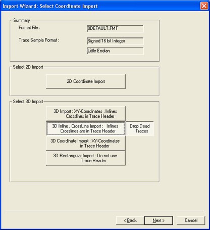
- Select <3D In-line,
Cross-Line Import> from the Select
Coordinate Import window if your in-line and cross-lines are in
the trace header, but your x/y coordinates are not.
 View image

- >Once you select this option,
the <Leave Dead Traces> button will
appear in the window. Dead traces are assumed to have incorrect trace
headers, so WinPICS interpolates
x/y’s for the dead traces. Click on this button to drop dead traces and
the button will read <Drop Dead Traces>.
Dropped dead traces will not be displayed on your seismic, but are not
removed from your SEG-Y file. If you plan to import additional processing
versions,
do not drop dead traces.
- Click <Next> at the bottom
of the Select
Coordinate Import window. A
new window will open.
 View image

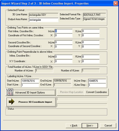
- Edit
the labeling for the in-lines and cross-lines under Labeling
In-line/X-line, if necessary. These values were read from the trace
headers in your file. If the file has been decimated, enter an
In-line Step. The End In-line
is automatically updated.
- Enter
the x/y coordinates for two in-line/cross-line locations on a single in-line
under Defining Two Points on the SameIn-line. This provides the in-line bin size of your file. Use the
º
key to move between boxes.
- Enter
the x/y coordinates for a third point that is on the same cross-line as
the first or second point under Defining
Point Perpendicular to Above In-line. This
provides the cross-line bin size and geometry of the 3D data area.
- Set
Advanced 3D Import Options,
as appropriate.
- Toggle
the Convert Coords option if you
need to modify the coordinates projection.
- Click
the <Process 3D Coordinate Import>
button. A dialog box will open summarizing the in-line and cross-line
bin size and the angle between in-lines and cross-lines. Click <OK>
if these are correct.
- Click <Preview Map> to see the coordinate
locations of your 3D data area on your project map.
- Click
on <Next> to proceed to the Line
Intersections and Seismic Import Properties dialog box.
- The Total
Number of In-line/X-line in SEG-Y File
section displays the number of in-lines and cross-lines that the wizard
found in your file. If these numbers are incorrect, it is very likely
that there is a problem with the in-line and cross-line numbering in your
file.
What do you want to do?
 View image
 View image
 View image