Open topic with navigation
Advanced
3D Import Options
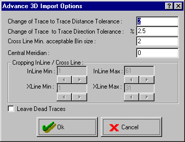
The Advanced 3D Import Options dialog box
provides an error check for your coordinates. Access this dialog box by clicking on
the <Advanced 3D Import Options> button
in one of the four 3D coordinate import methods: 3D
Import from Trace Header, 3D
In-line/Cross-Line Import, 3D Coordinate
Import, and 3D Rectangular Import.
Defaults for these values are usually okay, but you
may need to set them higher for some coordinate systems.  View image

This dialog box has the following options:
- Change of Trace-to-Trace
Distance Tolerance – This is the amount of change in the trace
to trace separation distance that is acceptable. It is expressed in meters
or feet, depending on the unit of your data. The default value of 2 is
usually appropriate. If the first two traces in your 2D line are separated
by 50 m, then a separation of more than 52 m or less than 47 m in other
adjacent traces, would cause WinPICS to report an error. You can read the trace to trace separation in the
‘Dis’ column of the trace header in the Trace
Header tab. If you are working in feet, you may need to increase this
number to 5 or even 10.
- Change
of Trace-to-Trace Direction Tolerance – This is the amount
of directional change from one trace to another that is acceptable. It
is expressed as a percentage. The default value of 2.5% is usually appropriate.
If the direction changes more than 2.5%, an error is reported.
- Cross Line Min.
Acceptable Bin Size – This is the minimum acceptable cross-line
bin size, expressed in meters or feet, depending on the unit of your data.
The default value of ‘2’ is usually acceptable. If the bin size is less
than 2 meters (or feet), WinPICS will report an error. This allows for round-off errors, but still alerts
you if the wizard is reading receiver or source coordinates rather than
CDP bins. If you are working in feet, you may need to increase this number
to 5 or even 10.
- Central Meridian
– This parameter is optional and for your reference only.
- Cropping In-line/Cross-Line
– to be implemented.
- Leave Dead Traces
– Click the Leave Dead Traces
button to toggle Drop Dead Traces.
(The wizard will do what the button says.) Dropped dead traces will not
be assigned coordinate locations and are not displayed in your seismic
window. (The traces are not removed
from your SEG-Y file.) If you plan to import additional processing versions for your data area, do not drop
dead traces.
What do you want to do?
 View image
 View image