Open topic with navigation
Wavelet
Matching / Transfer Function - Overview
The wavelet matching/transfer
function is used to apply an operator to a seismic dataset to tie it with
another seismic dataset. It is particularly useful for applying non-linear
phase corrections.
Opening the Wavelet Matching/Transfer Function
Right click on the seismic line you wish to
analyze or adjust and select from the shortcut menu (or press <t>
on your keyboard). Note that the seismic line must be part of a fence
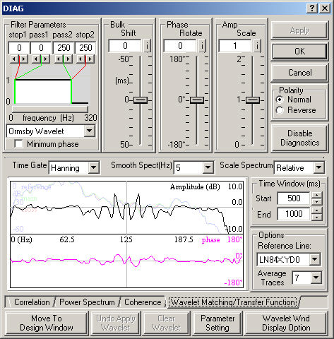
in order to use the diagnostic line tie functions. Click on the Wavelet Matching/Transfer Function tab.
 View image

Understanding the Wavelet Matching/Transfer Function
Window
- The black
curve is the ratio of the amplitude spectra. Zero values indicate similarity
of the active and reference amplitude spectra. The power spectrum of the
active seismic line is also shown in the background in grey.
- The pink curve is the phase spectrum. Together,
the amplitude and phase spectra define the operator that when applied
to the active
seismic, would match it with the reference
seismic.
As you make adjustments,
the power spectrum is recalculated and the seismic is automatically updated.
Using the Wavelet Matching/Transfer Function
- Define your area of interest by specifying a start
and end time under Time Window.
- Select which Reference Line
you which to use.
- Enter the number of traces to use in the wavelet
matching/transfer function under Average Traces.
- Select Rectangular,
Hanning,
or Hamming
under Time Gate to define the
shape of the cutoff applied to the function in the time domain to transfer
it to the frequency domain.
- Set the amount of smoothing for the power spectrum
under Smooth Spect (Hz).
- Set the Scale Spectrum as Relative or Individual.
- Fine-tune the operator by
clicking on Move
to Design Window. The Move
to Design window allows you to select amplitude
and/or phase corrections, set the operator length, manually edit the amplitude
or phase spectrum, and open a saved wavelet.
- Apply the operator from the
Move to Design window.
- Corrections to amplitude, bulk shift, and polarity are stored in a header
file and applied to traces and picks for display, picking, plotting, and
export.
- The
seismic line must be part of a fence display to enable diagnostics. See
fence considerations for
seismic ties.
For more information about the options on this tab, see the Tie with Diagnostics dialog box.
Display Options
Click <Wavelet Wnd Display Option> to open the Display Option for Transfer Function dialog box, where you can change curve positions, curve colors, and axis ranges, or enable cursor tracking.
What do you want to do?
Creating Fences - Overview
Cross-Correlation - Overview
Display Option - Wavelet Matching Window
Line Ties - Overview
Spectral Analysis - Overview
 View image
 View image